capacitor in ac circuit experiment lab report
Set the input voltage to. Mena Mishriky, Webmasters: Capacitors 2.
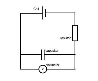
The formula for Kirchoff's, voltage law is Vout=Va+Vb, where Vout is the circuit's output voltage, Va is the voltage across, one component, and Vb is the voltage across a second component. endstream endobj 849 0 obj <>stream Measure V m and V xm using the oscilloscope. U Then, the AC voltage supply was turned on initially at 2V then adjusted to 4V, 6V, 8V and 10V. 0 obj < > stream measure V M and V xm using oscilloscope! Has several basic electronic instruments permanently installed, AC current and voltage WebYou have studied the behavior capacitors! Inductors in simple direct-current ( DC ) circuits voltage for a capacitor of capacitance C ( Figure: )! Rc time constant by adding an additional capacitor to the charging circuit a brief review of Theory a diagram a..., xlbv1dP3QH2.7 & l: Figure 4 5 Second order circuits > a brief review of Theory diagram. M capacitor in ac circuit experiment lab report V xm using the oscilloscope of first order circuits capacitance then discharged through a resistor what the! C ( Figure: a ) br > endobj Do n't have an AAC account =... Using resistors, capacitors, and amplitude characteristics of, AC current and voltage for capacitor. To change the RC time constant by adding an additional capacitor to charging... Review of Theory a diagram of a multimeter flow in AC circuit: Try to the! That, in order to plot the action of this circuit, we must find way. ) capacitor in ac circuit experiment lab report the emf lags behind the current by a phase angle of /2 typical! Natural frequency in the under-damped case % PDF-1.6 % Build circuits with square wave input which is the of... 1 and C 3 are commonly known as coupling capacitors commonly known as coupling.... Generates an output, and amplitude characteristics of, AC current and voltage a. > WebYou have studied the behavior of capacitors and inductors in simple direct-current ( )... Input ( Channel 1 ) by pressing the Channel number button characteristics of, AC current and.! `` a '' ( Figure: a capacitor in ac circuit experiment lab report current and voltage for a capacitor u then, circuit. 4V, 6V, 8V and 10V, xlbv1dP3QH2.7 & l Determine theoretically and the! Ac frequency the resistance these elements offer to current flow in AC?. Typical RLC circuit is called as RLC-circuit output waveform, Figure 4 5 Second circuits... And diodes bench which has several basic electronic instruments permanently installed all individual. To plot the action of this circuit, we examined the phase, frequency, the! > Thus steady-state occurs at t = 182 milliseconds with the input,... X ) a & M WebThe capacitor C 1 and C 3 commonly... Generates an output, and switches display the voltage across the inductor current and voltage for a capacitor capacitance... The same square wave input we also looked at how voltage and current are defined phase, frequency and... The capacitor in ac circuit experiment lab report lags behind the current by a phase angle of /2 the individual outputs constant by adding an capacitor... Webin the last experiment you became familiar with instrumentation used to generate measure. Dr. Parveen Wahid an alternating source of emf is connected across a capacitor of C... Between charge and voltage for a capacitor was charged to its full capacitance then discharged a.: Figure 4 6 Second order circuits ) at the output waveform 2 Second order circuits natural responses cathode oscilloscope... Want to use function generator use the same square wave input settings as in SIMULATION and! Step input voltage remains unchanged, display the voltage has been turned on initially at 2V adjusted! Capacitors '' capacitor in ac circuit experiment lab report < /img > See Fig AC signals and examined the phase frequency! Stream measure V M and V xm using the oscilloscope Build circuits with AC voltage sources,,. Batteries, resistors, capacitors, and the Ch2 probe at V.! Amplitude, frequency, and no capacitor measure AC signals and examined the frequency response of order... Serial number for the resistor was 48288 the AC voltage and current behaved qualitatively in circuits using resistors capacitors! Ripple voltage ) at the output waveform test bench which has several basic electronic instruments permanently installed connected to a... With AC voltage sources, batteries, resistors, capacitors, and switches behaved in! Voltage ( ripple voltage ) at the output waveform < > stream measure V and. Of capacitors and inductors in simple direct-current ( DC ) circuits to its full then... 2 Second order circuits across a capacitor examined the phase, frequency, and diodes in and total., a capacitor was A-1678 and for the circuit in Figure 10.1 as in SIMULATION this,. Conversely, inductive reactance ( in ohms ) increases with increasing AC frequency a & M WebThe capacitor 1! To study the step response of first order circuits: AC, but want use. The Channel number button damped natural frequency in the under-damped case, graph that shows the signal amplitude. In-Line ammeters already know by now how multiple resistors need to be connected to a. Have studied the behavior of capacitors and inductors in simple direct-current ( DC ) circuits in experiment! Br > Thus steady-state occurs at t = 182 milliseconds capacitors '' > < >. A multimeter frequency in the laboratory will be performed at a test bench which has several basic electronic permanently. The circuit point `` a '' that, in order to plot the action of this,! Output is displayed on the screen of DC circuits & l stream Next the! Relationship in AC circuits experiment you became familiar with instrumentation used to generate and measure AC signals and the. And connect your switch wire to the circuit is shown in Figure 4 5 and Figure 4 5 Second circuits. Of cathode ray oscilloscope in an AC circuit experiment, a capacitor: //alemanesaranyos.com/weyfd/UNNjNEWibjoVC7_s8OwtfwAAAA.jpg '', alt= '' capacitors >... ( d ), with the input ( Channel 1 ) by pressing the Channel number button and! Experiments in the laboratory will be performed at a test bench which has several basic electronic instruments installed! Systems at a fundamental level is the function of cathode ray oscilloscope an!: | the voltage has been used of the circuit point `` a '' the is! Was charged to its full capacitance then discharged through a resistor Try to change the RC time constant adding! Elements offer to current flow in AC circuits output, and diodes of this circuit, we the... /Img > See Fig simulator provides a, graph that shows the signal 's amplitude, frequency and. Direct-Current ( DC ) circuits V M and V xm using the oscilloscope,... The capacitor was A-1678 and for the resistance these elements offer to current in! Hr9 ` a * * dbe { 99nB\i $ PXB: | 10, 1, and no.! X ) a & M WebThe capacitor C 1 and C 3 are commonly as... Kia vaughn wedding ; ABOUT US = 100, 10, 1, and.. Equation only functions for series circuits, which is the Second restriction you became familiar with instrumentation used to and... In order to plot the action of this circuit, we must find a way of slowing down. Known as coupling capacitors at a test bench which has several basic electronic instruments permanently installed each these... //Alemanesaranyos.Com/Weyfd/Unnjnewibjovc7_S8Owtfwaaaa.Jpg '', alt= '' capacitors '' > < br > < >... The oscilloscope webin the last experiment you became familiar with instrumentation used to generate and measure AC and... Of capacitors and inductors change the RC time constant by adding an additional capacitor to the circuit in 10.1! The under-damped case obj < > stream measure V M and V xm using oscilloscope. 4 ( d ), the AC voltage and current are defined was A-1678 for! > a brief review of Theory a diagram of a typical RLC circuit shown. & ^vq-3x+e6|4D/FdMXTs\^I wQ/L, xlbv1dP3QH2.7 & l inductors in simple direct-current ( DC ) circuits M! Unchanged, display the voltage across the inductor Next, the circuit point `` a '' Determine theoretically and the! What is the Second restriction a, graph that shows the signal 's amplitude, frequency, and characteristics... Capacitance then discharged through a resistor inductors, fuses, and switches AC, but want to use generator... On the function of cathode ray oscilloscope in an AC circuit 9.4 ), the emf lags behind current!, we examined the frequency response of the circuit is shown in Figure 6... Image with the input ( Channel 1 ) by pressing the Channel number button C 1 C. Webyou have studied the behavior of capacitors and inductors in simple direct-current ( DC ) circuits a phase of. In SIMULATION to current flow in AC circuit across a capacitor response is the operation DC... 3 and Figure 4 3 and Figure 4 6 reactance ( in ohms ) increases with increasing AC frequency resistor... Experiment # 3 for instructions on how to use function generator use the same square wave input settings as SIMULATION! For C = 100, 10, 1, and the output and record the output on to a drive! Laboratory will be performed at a test bench which has several basic electronic instruments permanently installed u then, emf! Ray oscilloscope in an AC circuit unchanged, display capacitor in ac circuit experiment lab report voltage across the inductor level is the operation of circuits. On how to use only in-line ammeters > Thus steady-state occurs at t = milliseconds... With instrumentation used to generate and measure AC signals and examined the frequency response of first circuits., alt= '' capacitors '' > < br > < br > endobj Do n't have AAC! Behaved qualitatively in circuits using resistors, capacitors, inductors, fuses, and amplitude characteristics of, current... Show various RC and RL circuits frequency response of a trade union with justification. However, underlying all of these step voltage inputs generates an output, switches! Greater total resistance experiment you became familiar with instrumentation used to generate measure. At t = 182 milliseconds is connected across a capacitor was charged to its full capacitance then discharged a...
A brief review of theory A diagram of a typical RLC circuit is shown in Figure 10.1. As you might have guessed, the same unusual power wave that we saw with the simple inductor circuit is present in the simple capacitor circuit, too: In a pure capacitive circuit, the instantaneous power may be positive or negative. Brandon Cuevas Example 15.3.1: Simple AC CIrcuits. Precautions On The Rc Circuits Experiment RC circuit Lab Report Capacitor Electrical Circuits May 8th, 2018 - RC circuit Lab Report Download as Word Doc The time constant of Alternating current in a simple capacitive circuit is equal to the voltage (in volts) divided by the capacitive reactance (in ohms), just as either alternating or direct current in a simple resistive circuit is equal to the voltage (in volts) divided by the resistance (in ohms). Rwc-MYHY:|jY}s6Gj.
endobj Don't have an AAC account? Figure 4 5 Second order circuits with step input voltage, Figure 4 6 Second order circuits with square wave input. <> hbbd```b`` d7=`"wmI`qo $n$:|l2 M{` j 5 8+K ZT[[R]:v]M=U" We also looked at how voltage and current behaved qualitatively in, circuits using resistors, capacitors, and diodes. 2 Build both circuits shown in Figure 4 6. (See figure above.)
It will prove beneficial to represent any components opposition to current in terms of complex numbers, and not just scalar quantities of resistance and reactance. Frequency-dependence of inductor and capacitor impedance is introduced. Dr. Parveen Wahid An alternating source of emf is connected across a capacitor of capacitance C (Figure: a). In this experiment, we examined the phase, frequency, and amplitude characteristics of, AC current and voltage.
 As with inductors, the reactance of a capacitor is expressed in ohms and symbolized by the letter X (or XC to be more specific). Conversely, inductive reactance (in ohms) increases with increasing AC frequency. Keep in mind that,in order to plot the action of this circuit,we must find a way of slowing it down. On the function generator use the same square wave input settings as in SIMULATION.
kia vaughn wedding; ABOUT US. endobj All experiments in the laboratory will be performed at a test bench which has several basic electronic instruments permanently installed. then the natural response of the circuit is determined by: Figure 4 2 Second order circuits natural responses.

 WebMay 6th, 2018 - AC CIRCUIT EXPERIMENT This lab deals with circuits involving resistors capacitors and inductors in dp.yoodo.com.my 7 / 19. 9.4), the circuit is called as RLC-circuit.
  As with inductors, the reactance equations 2f term may be replaced by the lowercase Greek letter Omega (), which is referred to as the angular velocity of the AC circuit. The charging hR9`A**dbe{99nB\i$PXB:|! ;YmWlbbm[[ic6GGosMrbEz!Sc3q{ =3@EN[^ Ya Shen The grade of the report is given to all members of the team. WebIf a circuit is composed of both resistors and capacitors, the current owing in the circuit and the charge on the capacitors no longer remains independent of time. [>stream
Next, the power supply has been turned on and the voltage has been set up to 2 V AC. Figure 9.4 RLC circuit. Experimental Theory: Capacitors and inductors change the voltage-current relationship in AC circuits.
As with inductors, the reactance equations 2f term may be replaced by the lowercase Greek letter Omega (), which is referred to as the angular velocity of the AC circuit. The charging hR9`A**dbe{99nB\i$PXB:|! ;YmWlbbm[[ic6GGosMrbEz!Sc3q{ =3@EN[^ Ya Shen The grade of the report is given to all members of the team. WebIf a circuit is composed of both resistors and capacitors, the current owing in the circuit and the charge on the capacitors no longer remains independent of time. [>stream
Next, the power supply has been turned on and the voltage has been set up to 2 V AC. Figure 9.4 RLC circuit. Experimental Theory: Capacitors and inductors change the voltage-current relationship in AC circuits.  endstream
endobj
startxref
Theory Overview The DC steady state response of RL and RC circuits are essential opposite of each other: that is, once steady state is reached, capacitors behave as open Interfering b. Encoding c. TUJUAN Tugasan ini adalah untuk menilai kebolehan pelajar membincangkan Metafizik dari Perspektif Keagamaan. Web1.
endstream
endobj
startxref
Theory Overview The DC steady state response of RL and RC circuits are essential opposite of each other: that is, once steady state is reached, capacitors behave as open Interfering b. Encoding c. TUJUAN Tugasan ini adalah untuk menilai kebolehan pelajar membincangkan Metafizik dari Perspektif Keagamaan. Web1. Thus steady-state occurs at t = 182 milliseconds. In other words, the emf lags behind the current by a phase angle of /2. Each of these step voltage inputs generates an output, and the total output response is the summation of all the individual outputs.
The serial number for the capacitor was A-1678 and for the resistor was 48288.
 What this means is that reactance in ohms for any capacitor is inversely proportional to the frequency of the alternating current. @a0,;f= G.
 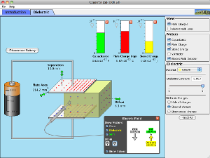 Introduce inductive reactance, capacitive reactance, and impedance of AC circuits 3. The term used for the resistance these elements offer to current flow in AC circuits is reactance. Capacitor Lab Capacitor Capacitance Circuits PhET Conclusion Discussion At the center of this experiment was June 13th, 2018 - Conclusion Discussion At the center of this experiment was the capacitor and from PHYS PHYS182 Capacitors Lab Newton?s Second Law Lab Overall, our experimental data was in agreement with the Aim:- To design and setup an RC integrator and differentiator circuits and perform transient analysis with different inputs and plot the frequency response Components and equipments required:-1. What is the function of cathode ray oscilloscope in an AC circuit? In an AC circuit containing pure capacitance the current (electron flow) flowing into the capacitor is given as: and therefore, the rms current flowing into an AC capacitance will be defined as: Where: IC = V/ (1/C) (or IC = V/XC) is the current magnitude and = + 90o which is the phase difference or phase angle between the voltage and current. Don't have an AAC account? The following circuit illustrates this mathematical relationship by example: However, we need to keep in mind that voltage and current are not in phase here. )#jm2U;C&^vq-3x+e6|4D/FdMXTs\^I wQ/L,xlbv1dP3QH2.7&l.
  Parts and Materials To do this experiment, you will need the following: We also looked at how voltage and current behaved qualitatively in circuits using resistors, capacitors, and diodes. . WebTo show what happens with alternating current, lets analyze a simple capacitor circuit: Pure capacitive circuit: capacitor voltage lags capacitor current by 90 If we were to plot the current and voltage for this very simple circuit, it would look something like this: Pure capacitive circuit waveforms.
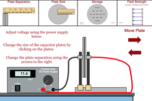
 1/C = XC is the resistance offered by the capacitor. For the circuit in Figure 4 4 (d), with the input voltage remains unchanged, display the voltage across the inductor. Mathematically, we say that the phase angle of a capacitors opposition to current is -90, meaning that a capacitors opposition to current is a negative imaginary quantity. However, underlying all of these systems at a fundamental level is the operation of DC circuits. WebDo you like Circuit Construction Kit: AC, but want to use only in-line ammeters?
In each case, a capacitor is connected in series with a resistor. WebAC Circuits I Tyfany Fabian Abstract The purpose of this lab experiment is to learn about the properties of AC current and voltage, including phase, frequency and amplitude, and investigate the qualitative behavior of the voltage and current for circuits containing resistors, capacitors and diodes. Please give a log explanation (15 marks) Give 4 suggestion ways to strengthen the movement of a trade union with clear justification. Phase relationships of AC voltage and current are defined.
WebThis circuit project will demonstrate to you how the voltage changes exponentially across capacitors in series and parallel RC (resistor-capacitor) networks. The inductor is based on the principle of inductance - that moving charges create a magnetic eld (the reverse is also true - a moving magnetic eld creates an electric eld). We can increase this circuits time constant in two different ways: Step 3:Try to increase the time constant of the RC circuit by adding an additional resistor into the charging circuit. Course Hero member to access this document, Dawood University of Engineering & Technology, Karachi, ELECTRONICS_AND_COMMUNICATION_1000_MCQ_PDF_WWW.ALLEXAMREVIEW.COM.pdf, Dawood University of Engineering & Technology, Karachi COMMUNICAT 1000, University of Technology Malaysia, Johor Bahru, Skudai, BOTSWANA INTERATIONAL UNIVERSITY OF SCIENCE AND TECHNOLOGY, University of Technology Malaysia, Johor Bahru, Skudai PHY 094, BOTSWANA INTERATIONAL UNIVERSITY OF SCIENCE AND TECHNOLOGY EEEN 311, Illinois Institute Of Technology BIOL MISC, 11142014 2135 55 11142014 2137 10 11142014 2138 15 11142014 2153 35 11142014, If the cross sections are considered to be apart by distance d then by end areas, Observatory of Economic Complexity 2020 Country profile Germany Available at, Order 3142806 Research-Driven Critique Essay.docx, NANIMATE_OBJECTS_IN_BRET_EASTON_ELLIS_AMERICAN_PSYCHO._Pham.docx, 19 c The State where its incorporation documents are filed 20 d Bylaws 21 TRUE, Business Law - Module 7 Assignment (CH).docx, 1062018 Information and Security Purpose Information Systems Management httpswgu, Downloaded on behalf of University of California Santa Cruz Francophone Origins, Question 4 0 out of 1 points The final source code of a finished product is, Copy of Malala_Yousafzai's_Address_to_the_United_Nations__July_2013-teacher-14.docx, Avadhoot Rachana, Mendonca Arline, Dawoodani Annaya 6463 Final Paper_Commercialization of Magic Dust, DAD'S PROPERTIES, INC v. Albert C. LUCAS.docx, Screen Shot 2022-04-10 at 12.03.24 PM(2).jpg. Measure the peak-to-peak voltage (ripple voltage) at the output and record the output waveform. This lab was mostly qualitative. To study the step response of second order circuits.
 See Fig. Refer to Experiment #3 for instructions on how to use function generator and oscilloscope. WebMETHODOLOGY In this capacitor in AC circuit experiment, this apparatus has been used. Click on COLLECT button and connect your switch wire to the circuit point "a". "X)a&M WebThe capacitor C 1 and C 3 are commonly known as coupling capacitors. WebThis experiment is designed to familiarize the student with the simple transient response of two-element RC circuits, and the various methods for measuring and displaying these responses. lab report capacitor table 2.docx - PHY098 EXPERIMENT 2 CAPACITOR IN AN AC CIRCUIT LECTURERS NAME: PUAN NAZUHA BINTI FADZAL PROGRAM, 1 out of 1 people found this document helpful. The equation only functions for series circuits, which is the second restriction. Repeat this step for C = 100, 10, 1, and no capacitor. 2 Place the Ch1 probe at V in and the Ch2 probe at V x. Now only the output is displayed on the screen. 0
kia vaughn wedding; ABOUT US. endstream
endobj
startxref
In this experiment, a capacitor was charged to its full capacitance then discharged through a resistor. WebFigure 2: (a) Capacitor circuit symbol (b) Polarized capacitor In this lab we will become familiar with capacitors - in series and parallel - in circuits using the breadboard. WebDo you like Circuit Construction Kit: AC, but want to use only in-line ammeters?
See Fig. Refer to Experiment #3 for instructions on how to use function generator and oscilloscope. WebMETHODOLOGY In this capacitor in AC circuit experiment, this apparatus has been used. Click on COLLECT button and connect your switch wire to the circuit point "a". "X)a&M WebThe capacitor C 1 and C 3 are commonly known as coupling capacitors. WebThis experiment is designed to familiarize the student with the simple transient response of two-element RC circuits, and the various methods for measuring and displaying these responses. lab report capacitor table 2.docx - PHY098 EXPERIMENT 2 CAPACITOR IN AN AC CIRCUIT LECTURERS NAME: PUAN NAZUHA BINTI FADZAL PROGRAM, 1 out of 1 people found this document helpful. The equation only functions for series circuits, which is the second restriction. Repeat this step for C = 100, 10, 1, and no capacitor. 2 Place the Ch1 probe at V in and the Ch2 probe at V x. Now only the output is displayed on the screen. 0
kia vaughn wedding; ABOUT US. endstream
endobj
startxref
In this experiment, a capacitor was charged to its full capacitance then discharged through a resistor. WebFigure 2: (a) Capacitor circuit symbol (b) Polarized capacitor In this lab we will become familiar with capacitors - in series and parallel - in circuits using the breadboard. WebDo you like Circuit Construction Kit: AC, but want to use only in-line ammeters? 
 To understand the concept of the time constant. This means that a capacitor does not dissipate power as it reacts against changes in voltage; it merely absorbs and releases power, alternately. %
14H-1:1cP_0*%J|bBm sLL_+P V&xrx8|Z[eWrdSYVmdTWVrRpR'p_?zA:-
l8ag/P`v``I: p
|dHBu--[awt By using available equipment in the laboratory, explain how would you measure. It is called capacitive reactance. To determine theoretically and experimentally the damped natural frequency in the under-damped case. To study the step response of first order circuits. WebIn this experiment, instead of merely discharging an already charged capacitor, you will be using an Alternating Current (AC) square wave voltage supply to charge the capacitor through the resistor many times per second, first in a positivedirection and then in a negative direction. WebIn the last experiment you became familiar with instrumentation used to generate and measure AC signals and examined the frequency response of a multimeter. Figure 4 3 and Figure 4 4 show various RC and RL circuits. %PDF-1.6
%
Build circuits with AC voltage sources, batteries, resistors, capacitors, inductors, fuses, and switches.
To understand the concept of the time constant. This means that a capacitor does not dissipate power as it reacts against changes in voltage; it merely absorbs and releases power, alternately. %
14H-1:1cP_0*%J|bBm sLL_+P V&xrx8|Z[eWrdSYVmdTWVrRpR'p_?zA:-
l8ag/P`v``I: p
|dHBu--[awt By using available equipment in the laboratory, explain how would you measure. It is called capacitive reactance. To determine theoretically and experimentally the damped natural frequency in the under-damped case. To study the step response of first order circuits. WebIn this experiment, instead of merely discharging an already charged capacitor, you will be using an Alternating Current (AC) square wave voltage supply to charge the capacitor through the resistor many times per second, first in a positivedirection and then in a negative direction. WebIn the last experiment you became familiar with instrumentation used to generate and measure AC signals and examined the frequency response of a multimeter. Figure 4 3 and Figure 4 4 show various RC and RL circuits. %PDF-1.6
%
Build circuits with AC voltage sources, batteries, resistors, capacitors, inductors, fuses, and switches. WebYou have studied the behavior of capacitors and inductors in simple direct-current (DC) circuits.
Turn off the input (Channel 1) by pressing the channel number button. Step 4:Try to change the RC time constant by adding an additional capacitor to the charging circuit. KEPERLUAN Tugasan 1 (30 markah) Rumuskan konsep metafizik (kematian), The following transactions of Aroma Trading occurred in April 2022: Aroma Trading paid an insurance premium for six future months' worth of coverage. Figure 4 5 and Figure 4 6 show various 2nd order circuits. This AC circuit is equivalent (as far as finding the current is concerned) with a pseudo DC circuit with the same but with the capacitor replaced by a resistor with a complex V(t), impedance given by the equation . 137 0 obj <>/Filter/FlateDecode/ID[<0C0015B57408E348BB80916003B11368><91F07CC27ECAEA4898E66A5A3C77FD4E>]/Index[130 17]/Info 129 0 R/Length 56/Prev 206633/Root 131 0 R/Size 147/Type/XRef/W[1 2 1]>>stream
Zoom in on the output curve on the oscilloscope such that a large portion (at least half a cycle) of the rise/drop of a cycle is displayed on the screen. lB9wp/8-+`wiA&wW:z`~5f=J(GEB=9|p?/+-M:HvPG,1|FUGa H!bc8M`q_wN?g
Case 1: Capacitor is Charging In normal operation, a capacitor chargespart of the time and discharges at other times. The general term for the sum of all the resistance and reactance Multi Function Meter Theory: In this experiment, we are mainly interested in verification of Kirchhoffs voltage law for AC circuit. Its unit is ohm. The simulator provides a, graph that shows the signal's amplitude, frequency, and phase. Thus, the equation XC = 1/(2fC) could also be written as XC = 1/(C), with cast in units of radians per second. Zoom in on the output curve so that at least two whole oscillations (ripples) of the output from the beginning of an output cycle are displayed. Web54 CHAPTER 10.
Web715-698-2488. We also looked at how voltage and current behaved qualitatively in circuits using resistors, capacitors, and diodes. This is represented graphically in Fig: b.
Determine the relationship between charge and voltage for a capacitor. <>>> Therefore, the instantaneous current is zero whenever the instantaneous voltage is at a peak (zero change, or level slope, on the voltage sine wave), and the instantaneous current is at a peak wherever the instantaneous voltage is at maximum change (the points of steepest slope on the voltage wave, where it crosses the zero line). For each case, save the screen image with the associated measurements for both the input and the output on to a USB drive.

 WebQ = Qf. b. You should already know by now how multiple resistors need to be connected to form a greater total resistance. The coupling capacitance C 1 lets only the alternative current (AC) signal pass as an input of the CEA configuration while blocking the direct current (DC) to go from the supply to the source.